21+ 3 5Mm Audio Wiring Pin Diagram PNG. I understand everything that is on the diagram, except the aux audio and aux ground part. I have cut the male to male 3.5 mm audio jack and solder two wires, but one should a female 3.5 mm.
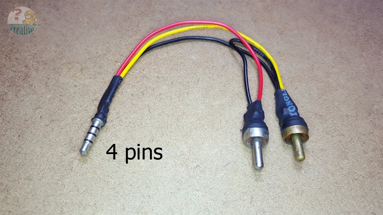
Connect 3.5 mm Headphone (4 pins) to Stereo audio jack ... from i.ytimg.com Note that the subaru wiring diagram numbers the pins differently than on the scoobymods picture above ***8212; Unless wiring details are available, cannot make own cable if you have few usb cables to spare, then cut one end of cable, take out wires, strip tip of wire, connect usb, then measure voltages in cable, then check by connecting it to some audio input circuit, by this method only you will be able to trace. Also, for hobbyists 3.5mm audio jack is a useful components for projects that plug into headphone jacks.
Looking at the back of the radio they are when nothing is plugged in, the factory 3.5mm jack also shorts the audio l/r input lines to audio ground (so if you want to splice in a second audio cable in addition.
All other speakers are connected by a phono lead except front right which. If you only need a mono input, the left and right audio channel wires can be connected together. For using a 3.5mm audio male jack for your projects or prototypes, you have to solder wires with the pins of the jack. Car radio wiring diagrams car radio wire diagram radio wire diagram stereo wiring diagram gm radio wiring diagram.

0 Response to "3 5Mm Audio Wiring Pin Diagram"
Post a Comment